
FIG. 1: CWKA MANUFACTURING ANALYSIS
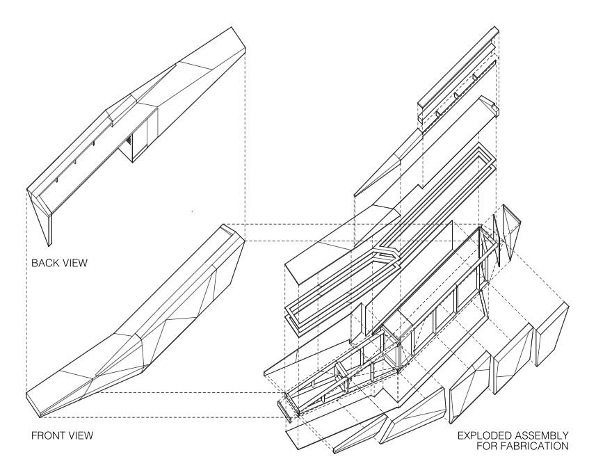
FIG. 2: EXAMPLE OF SHOP FLOOR 3D MODEL

FIG. 3: SAMPLE OF MILL PART 3D MODEL

FIG. 4: PROGRAMMING SOFTWARE INDICATING TOOL PATH INFORMATION

FIG. 5: PROJECT CYCLE DIAGRAM
INTRODUCTION
In response to industry trends and an internal assessment of project requirements, CW Keller has recently completed a radical restructuring of its design-manufacturing process.
Due to prevailing trends within the AEC industry and an open approach to experimentation, CW Keller has built a portfolio specializing in geometrically complex project types. During the past 15 years of operation, CW Keller has built upon its expertise of the wood medium to quickly incorporate a diverse selection of additional mediums such as solid surface, complex concrete formwork, and advanced metal fabrication into its client offerings.
This diversification of project work provided many initial challenges, and the company put in the requisite efforts to first identify new development methodologies and quickly build expertise. These changes were initially focused on the engineering department as 3D modeling replaced traditional CAD as the primary means of project development and documentation. Over time, downstream processes were revised as lapses in development were observed, leading to an effective but piece-meal production workflow.
After adding our large 5 axis cnc machine (a pivotal addition to our working capabilities) the company committed itself to a holistic redevelopment of its project development cycle. A small team was tasked with evaluating the existing production process and establishing a new product development process for the company. Through an internal audit, it was determined that our existing development process was out of date and did not take full advantage of our engineering and machining capabilities. By generating 2D drawings for project approval and build documentation, CW Keller was not leveraging the data inherent in its high fidelity 3D models.
By researching the Automotive, Aerospace, and traditional Millwork industries, the team was able to define CWKA’s position as a manufacturer. Through this exercise, and using a Model Based Definition (MBD) process as a backbone, the team was able to identify a working methodology that would best serve our unique position in the digital fabrication space (Fig. 1).
IMPLEMENTATION
The implementation strategy was loosely structured around three criteria: Personnel, Procedure, and Technology.
PERSONNEL
We realized employee training and development is a critical step in properly implementing a new project process. Historically, shop drawings were used for in-house communications. Where work in progress required additional visual aids, engineers typically used a laptop on the shop floor to navigate a 3D model. This approach, while useful at the moment, limited the capacity of our highly-specialized team of fabricators and millworkers to access project information efficiently.
We developed a strategic training program with the goal of providing technical training to our mill and fabrication team. The training was structured around a once a week live session with weekly assignments for review. Newly acquired skills were put into immediate practice during the time in between sessions. To ensure a high adoption rate, active projects were structured to increasingly leverage 3D fabrication content and engineering team members remained on call to support the mill and fabrication teams as required (Fig. 2)
Over time this training provided the mill and fabrication departments the requisite skill set to have on-demand access to fabrication content for active projects. This approach in project development opened up a new dialogue between members of the team across each department.
TECHNOLOGY
To better support the newly trained mill and fabrication team, upgrades were made to our in-house technical solutions. First, the company transitioned to a cloud-based file sharing solution, removing significant information sharing roadblocks. Second, laptops were purchased for distribution to the shop floor and mill. In tandem, these strategic changes guaranteed the factory floor access to on-demand digital manufacturing information.
On the software front, our team acquired and implemented machining simulation software to better predict the complex movements of our 5 axis CNC machine. Implementing machining simulation software, along with enhanced accessibility to 3D modeling data, allowed our mill department to reduce machining errors and increase the accuracy of parts used in our projects.
PROCEDURE
With training and technology upgrades in place, we developed new procedures to best leverage CW Keller’s new internal capabilities.
Our project hand-offs now include a version-controlled 3D Model (Fig. 3). This model will typically include notation for significant job details, critical dimensions, and annotated parts defined by material and finish. These data-rich 3D models allow our teams to quickly identify parts in multi-material complex builds. Critical pieces of information that are difficult to capture in traditional 2D shop drawings are more easily found, and potential engineering errors are reviewed and addressed earlier in the design process.
Additionally, our Mill department now receives targeted 3D Model (Fig. 4) information that allows for our machine operators to better understand the design intent of parts and clarify critical points for on-the-fly part machining calibration.
CONCLUSION
The ability to produce complex parts efficiently has significantly reshaped our approach to engineering projects. Prior to developing more sophisticated machining strategies, CW Keller relied on the expertise of the fabrication team to resolve manual assembly problems on the shop floor. With the addition of machining verification software and 3D model review capabilities, CWKA can now accurately produce more complex parts to simplify the overall assembly strategy on projects. This has led to significant savings in project run times and an overall increase in project quality.
NEXT STEPS
Based on the success of our process redefinition, CW Keller has now focused on a similar upstream process redefinition (Fig. 5). Initial analysis has provided a clear project roadmap, outlining the requisite steps and software solutions implemented by the team.
Future steps include an extension of in-house training to upstream project staff (project management, sales, and operations), evaluation of current software and hardware tools, and establishing new employee onboarding processes. Through continued refinement of this process, our team is confident CWKA can respond to increasingly sophisticated projects and remain an agile leader in custom feature element fabrication.